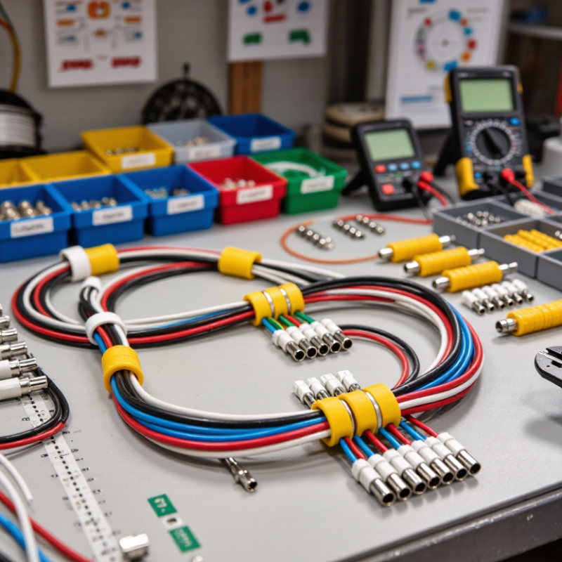
A wire harness assembly is an organized network of wires, terminals, connectors, sleeves, and protective coverings. It carries electrical power and signals between components in vehicles, appliances, industrial equipment, and electronic systems. Instead of routing separate wires through a machine, engineers group them into one structured assembly. This approach reduces clutter, supports safer installation, and makes maintenance more manageable. Each branch follows a planned path, while clips, labels, and conduit help control movement and protect insulation. At a workbench, technicians cut wires to specified lengths, strip the ends, crimp terminals, and secure connections inside suitable housings. They then inspect routing, continuity, polarity, and connector engagement. Small details matter. A loose crimp can cause intermittent operation, heat, or complete failure.
The working process begins with a circuit design and a detailed harness drawing. Manufacturing teams translate that information into cutting lists, assembly boards, testing procedures, and inspection records. Automated tools may improve repeatability, but experienced technicians still notice problems that machines can miss, such as awkward bends or excessive strain near a connector. In real projects, the process is rarely as simple as a clean diagram suggests. Space changes, component tolerances vary, and an apparently correct wire can still be difficult to install. That is why reliable manufacturers combine engineering review, controlled production, visual inspection, and electrical testing. The result is more than a bundle of cables. It is a carefully planned interface that helps an entire system work consistently. Mistakes remain possible. Good processes make them easier to find.
What Is a Wire Harness Assembly?
A wire harness assembly is an organized group of wires, terminals, connectors, and protective materials. It carries electrical power or signals between different parts of a machine. Instead of routing separate wires through a product, engineers bundle them into one controlled assembly. This approach improves installation speed, service access, and protection against abrasion.
A typical harness begins with a wiring diagram and a defined list of circuits. Technicians cut wires to measured lengths, strip the insulation, and attach terminals or connectors. They may add protective sleeves, clips, labels, seals, or heat-shrink tubing. Each part has a purpose. The outer covering can reduce movement, moisture exposure, and contact with sharp edges. The connectors also guide correct installation.
Testing is essential. Technicians usually check continuity, terminal placement, insulation condition, and connector locking. A visual inspection can catch loose strands or incorrect labels. Small errors matter. One misplaced terminal may interrupt an entire circuit. In real production, measurements sometimes need adjustment after assembly trials. That is not failure, but it deserves careful review. A harness that fits on a workbench may still bend poorly inside the finished equipment. Engineers should examine routing, bend radius, heat sources, and future maintenance before approving the design.
A wire harness assembly is a grouped network that directs power and signals through equipment. Its main components include wires, terminals, connectors, insulation, protection, and securing hardware. Each insulated wire contains a conductive core, usually selected for its current capacity and flexibility. Different wire sizes handle different electrical loads. Terminals attach wire ends to connector contacts or equipment points. A secure crimp is essential. Loose crimps can create heat, resistance, and intermittent faults.
Connector housings keep contacts aligned and prevent accidental separation. Some connectors include seals that block moisture, dust, and vibration. Protective components add another layer of safety. Heat-shrink tubing covers exposed joints, while braided sleeving or flexible conduit protects wire bundles from abrasion. Clips, ties, and mounting brackets hold the harness in position. Labels and color markings also help technicians identify circuits during installation and repair. Small details matter here.
During operation, the harness carries power, ground connections, and control signals between components. A technician normally checks continuity, insulation resistance, crimp quality, and connector engagement. Pull testing can reveal weak terminal connections before installation. Visual inspection remains useful, although it can miss hidden damage. In practical assembly work, a drawing may appear correct while the bundle bends poorly inside the final enclosure. That feedback may require a different wire length, clip location, or protective sleeve.
This chart shows the component quantities in a defined reference harness containing 12 conductors, two connector housings, and four retention points. During assembly, wires are cut and stripped, terminals are crimped to the wire ends, connector housings organize the circuits, and protective materials secure the bundle against abrasion, vibration, and movement.
Reference configuration: 12 conductors, 24 wire-end terminals, 2 connector housings, 4 retention clips, 1 protective sleeve, and 3 tape wraps.
Wire harness design begins with the application, not the connector. Engineers map every circuit, load, voltage, temperature range, and movement condition. They then select wire size, insulation, terminals, seals, and protective sleeving. A 2024 MarketsandMarkets report estimates the automotive wiring harness market could grow from about USD 57 billion in 2023 to more than USD 70 billion by 2028. That growth increases pressure for lighter, safer, and more traceable designs.
The process is not perfectly linear. A first drawing can be wrong. Engineers often adjust routing after checking bend radius, heat exposure, service access, and interference with nearby parts. Design software creates the schematic, board layout, cut list, and connector map. Preparation follows controlled steps: cut wires accurately, strip insulation without nicking conductors, crimp terminals with verified force, and apply labels. Technicians should inspect crimp height, pull strength, terminal position, and locking engagement. Continuity and insulation-resistance tests then expose hidden defects. The IPC/WHMA-A-620 standard is widely used to define workmanship expectations for cable and harness assemblies.
Tips: Keep branch points consistent. Leave enough slack for movement, but avoid loose loops. Record wire-lot details and tooling settings. A small sample should be tested before full production. This pause is useful. It can reveal a routing mistake that a neat drawing hides. Reviewers should also challenge assumptions, especially when current loads, vibration, or temperature data remain incomplete. “Looks correct” is not a test result.
Wire harness assembly turns separate wires into a protected, organized electrical network. Technicians begin by reviewing the wiring diagram, terminal specifications, and routing requirements. They cut each wire to length, then strip insulation without damaging the conductor. Crimping follows. A calibrated tool compresses the terminal around the wire strands. Poor crimp pressure can create resistance, heat, and early failure. IPC/WHMA-A-620 provides widely used acceptance criteria for these connections.
The next step adds labels, seals, clips, conduits, and protective tape. Workers insert terminals into plastic connectors until each locking lance clicks into place. They then arrange branches on a forming board or assembly fixture. The fixture controls bend radius and connector position. This detail matters in vehicles, industrial equipment, and appliances. Grand View Research’s 2024 automotive wiring harness analysis projects approximately 4.5% market growth annually through 2030, increasing pressure for repeatable production and inspection.
Testing comes after visual checks. A continuity tester confirms the correct electrical path, while a high-voltage test can identify insulation faults. Operators also compare connector locations against the drawing. A harness may pass electrically yet fail mechanically if a clip is loose. That weakness is easy to overlook. Experienced teams therefore inspect strain relief, sealing, and branch geometry before packaging. Manual assembly remains valuable, but it is not perfectly consistent. Better fixtures reduce variation, though they cannot replace careful judgment. (Sources: IPC/WHMA-A-620, Requirements and Acceptance for Cable and Wire Harness Assemblies; Grand View Research, Automotive Wiring Harness Market Report, 2024.)
| Step | Assembly Stage | Main Activity | Typical Materials or Inputs | Common Tools or Equipment | Key Quality-Control Points | Expected Output |
|---|---|---|---|---|---|---|
| 1 | Review Requirements | Confirm the wiring diagram, connector layout, circuit identification, wire lengths, branch locations, terminal types, and protection requirements before production begins. | Engineering drawing, bill of materials, wire list, connector specifications, revision-controlled work instructions. | Document-control system, drawing viewer, measuring scale, production checklist. | The current drawing revision, wire gauge, insulation type, color or identification code, and terminal part information must match the approved documentation. | A verified assembly plan and an approved list of materials. |
| 2 | Prepare Materials | Identify and stage wires, terminals, seals, connectors, splices, protective sleeves, clips, labels, and other components required for the harness. | Insulated wires, terminals, connector housings, cavity plugs, seals, grommets, braided sleeving, conduit, tape, and identification labels. | Material racks, barcode or lot tracking system, parts trays, calipers, component checklist. | Materials should be the correct type and size, free from visible damage, and protected from contamination, moisture, and mix-ups. | Correct materials staged in the required sequence for assembly. |
| 3 | Cut Wires to Length | Cut each wire according to the wire list, allowing for the required terminal strip length, routing path, bend radius, and branch position. | Specified wire sizes, colors, insulation types, and cut-length list. | Automatic wire cutter, measuring station, calibrated ruler, or cutting fixture. | Cut length must remain within the drawing tolerance. Wire ends should be square, clean, and free from crushed insulation or conductor damage. | Individual wire pieces identified by circuit, color, length, and destination. |
| 4 | Strip Insulation | Remove the specified amount of insulation from each wire end without nicking, cutting, or deforming the conductor strands. | Cut wires and terminal-specific strip-length requirements. | Automatic wire stripper, pneumatic stripper, manual stripper, or stripping fixture. | Strip length must match the terminal or splice requirement. No excessive exposed conductor, damaged strands, or remaining insulation should be present in the crimp area. | Prepared wire ends ready for crimping or splicing. |
| 5 | Install Seals and Accessories | Place wire seals, cavity plugs, heat-shrink tubing, backshell components, or other accessories onto the wire before the terminal is attached when the design requires this sequence. | Individual wire seals, heat-shrink tubing, protective boots, grommets, and backshell parts. | Seal insertion tool, positioning fixture, heat-shrink preparation tools. | Accessories must face the correct direction and be positioned far enough from the stripped conductor to avoid interference with crimping. | Wire ends prepared for terminal attachment with accessories correctly positioned. |
| 6 | Crimp Terminals | Place each terminal on the conductor and apply the specified crimp to secure both the conductor and, where applicable, the insulation support section. | Prepared wires and compatible terminals matched to conductor size and connector cavity. | Hand crimper, pneumatic crimper, automatic crimping machine, applicator, crimp-height gauge, microscope or magnifier. | The terminal must be fully seated in the applicator, conductor strands must be captured, the bell-mouth and wire brush must be acceptable, and the crimp must meet the terminal maker's specified dimensions and pull-force requirement. | A mechanically secure and electrically reliable wire-to-terminal connection. |
| 7 | Create Splices | Join two or more conductors when the circuit design requires a common electrical branch, then insulate and protect the joint. | Splice sleeves, crimp splice terminals, solder sleeves, heat-shrink tubing, or approved insulation materials. | Splice crimp tool, controlled heat gun, soldering equipment where permitted, splice fixture. | The splice must contain all required conductors, have no exposed conductor outside the approved area, and maintain the specified electrical resistance and mechanical strength. | An insulated branch connection with the correct circuit grouping. |
| 8 | Load Connector Housings | Insert terminated wires into the correct connector cavities until the terminals lock into place. Install secondary locks, cavity plugs, and backshells as specified. | Crimped wire terminals, connector housings, secondary locks, cavity plugs, and backshell components. | Terminal insertion tool, extraction tool, connector fixture, cavity map, magnifier. | Circuit position, terminal orientation, locking engagement, seal position, and connector keying must be correct. A light retention check should confirm that terminals do not back out. | Connectorized wire groups with the correct pinout and locked terminals. |
| 9 | Form and Route the Harness | Arrange wires on a form board or fixture to reproduce the final geometry, branch lengths, connector orientation, and bend directions. | Connectorized wire groups, form-board nails or pegs, routing clips, branch markers, and dimensional references. | Harness board, routing fixture, templates, positioning clips, measuring tools. | The harness must follow the approved path, maintain the required branch locations and bend radii, and avoid excessive tension, sharp bends, or connector twisting. | A harness that matches the intended physical layout and installation envelope. |
| 10 | Apply Protection and Bundling | Bundle and protect the wires using tape, conduit, braided sleeving, heat-shrink tubing, clips, grommets, or protective coverings. | Harness tape, corrugated conduit, braided sleeve, heat-shrink tubing, edge protection, clips, and labels. | Wrapping machine or hand tools, controlled heat gun, cutting tools, sleeve applicator. | Protection must cover the specified areas without restricting connector movement, blocking seals, covering identification, or creating excessive bundle pressure. | A mechanically protected and organized wire harness ready for testing. |
| 11 | Perform Electrical Testing | Test circuit continuity, verify the pin-to-pin connection map, check for short circuits, and measure insulation resistance when required by the design. | Completed harness, approved test program, circuit map, and test limits. | Harness tester, continuity meter, insulation-resistance tester, test adapter, fixture. | Every required circuit must connect to the correct destination. Unwanted shorts, open circuits, incorrect pin positions, and resistance values outside the approved limits must be rejected. | A tested harness with recorded electrical results and traceability. |
| 12 | Conduct Visual and Dimensional Inspection | Inspect the finished harness against the drawing, sample, or fixture for routing, component presence, markings, terminal seating, protection, and overall workmanship. | Finished harness, engineering drawing, inspection checklist, approved sample, and dimensional requirements. | Inspection lamp, calipers, measuring tape, go/no-go gauges, camera system where applicable. | No missing parts, exposed conductors, damaged insulation, loose terminals, incorrect labels, poor wrapping, or dimensional deviations should be present. | An accepted harness that meets both functional and physical requirements. |
| 13 | Label, Package, and Release | Apply identification labels, protect connectors and terminals, record inspection results, and package the harness to prevent bending, contamination, or impact during storage and transport. | Product labels, protective caps, bags, separators, packaging inserts, inspection records, and release documents. | Label printer, packaging station, barcode scanner, documentation system. | Labels must be legible and match the assembly record. Packaging should preserve connector integrity and prevent the harness from exceeding its allowable bend or compression limits. | A traceable, protected, and release-approved wire harness assembly. |

A wire harness works as the system’s organized nervous system. It groups wires, terminals, connectors, seals, clips, and protective sleeving into one controlled route. Power travels from a battery or supply to a load. Signals move between sensors, controllers, and actuators. Current returns through a dedicated wire or approved ground path. In a vehicle, one harness may connect a temperature sensor to a controller, then carry the controller’s command to a cooling fan. Fuses limit fault energy, while shielding can reduce electromagnetic interference.
The International Energy Agency reported nearly 14 million electric car sales in 2023. That growth increases the need for reliable high-voltage and low-voltage harness networks. A 2024 U.S. Department of Energy vehicle technology report also identifies wiring, connectors, and power electronics as important factors in vehicle efficiency and reliability. These figures show the scale, but not every field problem. Real assemblies are less tidy than diagrams. A connector may fit, yet poor terminal crimping can create heat, voltage drop, or intermittent signals. I have seen routing plans overlook vibration near a sharp bracket. That assumption is risky. Technicians therefore verify wire length, bend radius, pin position, pull-out force, insulation damage, continuity, and insulation resistance. IPC/WHMA-A-620 provides widely used acceptance guidance for cable and harness workmanship, although inspection alone cannot replace careful system design. The harness must be tested under realistic temperature, movement, moisture, and electrical-load conditions. Small details matter.